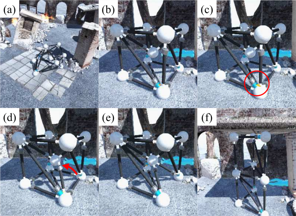
Fig. 1. Conceptual images of the VTT performing a search and rescue mission on a disaster site. (a) Locomotion; (b) arriving at the destination; (c) the master node grasping the target truss; (d) moving of the target truss; (e) finishing reconfiguration; (f) shoring up.
VTT comprises “members,” and “nodes.” Nodes are located at the vertices of VTT and connect members with passive spherical joints. Members can be actuated linearly to change their lengths. One of the main features of the Variable Topology Truss (VTT) system is self-reconfiguration. To conduct self-reconfiguration, the overall system should maintain its controllability during the process. This study proposes a design of a “master node” as a solution for the self-reconfiguration of VTT. Fig. 1. shows the self-reconfiguration scenario of VTT in a disaster site. A master node grabs the target member and moves its tip to the target node. By doing so, VTT can change its topology from cubic locomotion topology to shoring topology.
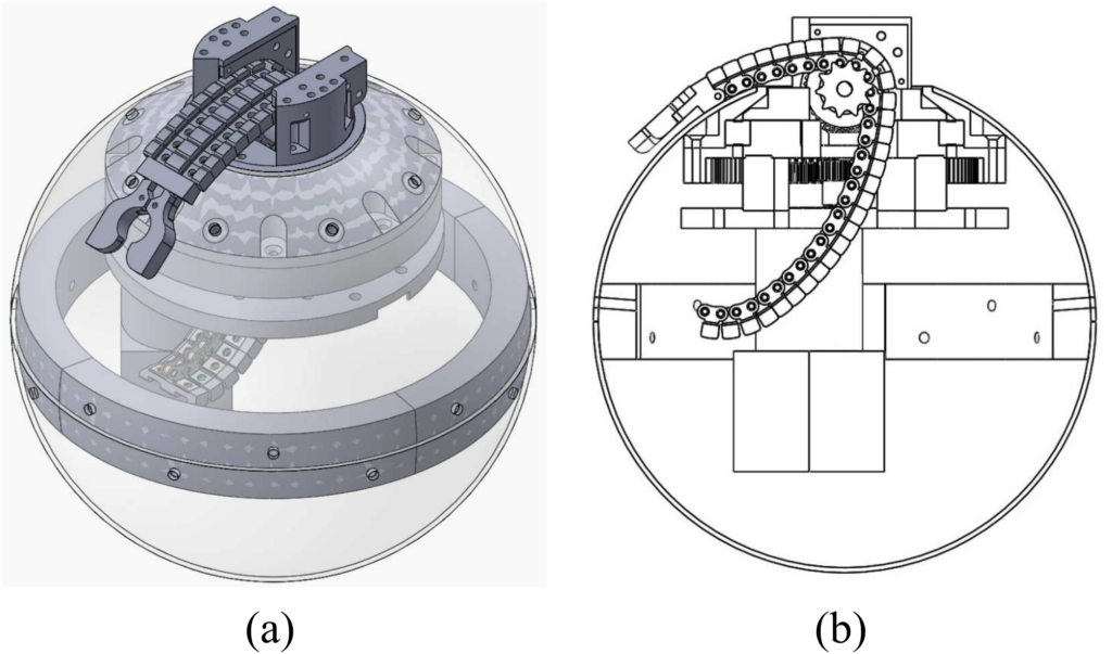
Fig. 2. The design of the “master node”. (a) Isometric view of the master node; (b) cross-sectional drawing of the master node.
We designed the master node to perform grabbing and moving the member. Fig. 2. shows the design of the master node. The master node should be able to provide spherical joint motion, which includes azimuthal angle and polar angle motion. The open-chain actuator was used for generating polar angle motion. An open-chain mechanism can control both pulling and pushing motions using the same actuator if the trajectory is properly constrained. We constrained the trajectory of the open-chain actuator by using the surface of a sphere and the shape of chain elements. The detailed design of the open-chain actuator is presented in Fig. 3. The azimuthal motion is achieved by a turret mechanism. Both the open-chain actuator and the turret mechanism were placed in a sphere.
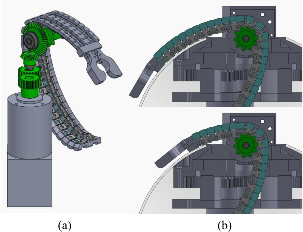
FIg. 3. Design of the open-chain actuator for polar angle motion: (a) Isometric view of the actuating parts and the chain structure; (b) polar angle movement of the open chain.
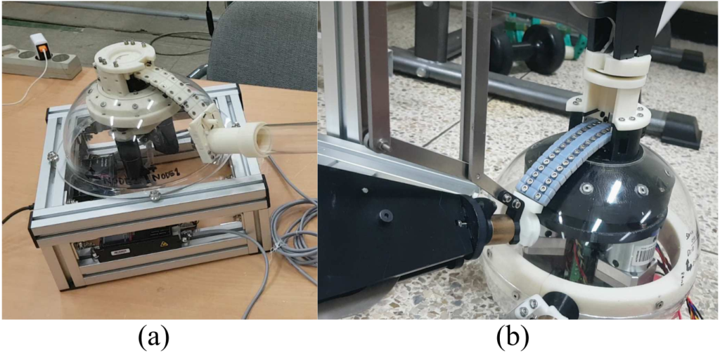
Fig. 4. Fabricated the master node prototype; (a) the master node prototype; (b) the assembled test bench for testing the reconfiguration process.
We fabricated a prototype of the master node to test its required functions. Most structural parts of the master node were made by using a 3 d printer. A polypropylene sphere was used as the sphere in the master node. The chain of the open-chain actuator was made by assembling 3d-printed cover parts on a standard commercial chain. (Tsubaki Inc., RS25K-1-U.S.) In the test, the spiral zipper and the passive member-end were attached to the gripper of the master node. The master node could move 0.125 RPM in the polar direction and 0.31 RPM in the azimuthal direction with the loads. Fig 4. shows the prototype of the master node and a picture of the master node moving test.
Pingback:relaxing smooth jazz
Pingback:peaceful music
Pingback:relaxing piano music
Pingback:jazz for happy xmas day
Pingback:músicas para treinar
Pingback:จุดเด่น – จุดด้อยของ Pgzeed
Pingback:สีกันไฟ
Pingback:บุหรี่นอกราคาถูก
Pingback:789 club
Pingback:อะไหล่อุตสาหกรรม
Pingback:sell weapons of destruction
Pingback:เช่ารถ alphard
Pingback:executive condo
Pingback:Sofwave รีวิว
Pingback:free rainbow six siege wall hacks
Pingback:เรียนต่อจีน
Pingback:Full Article
Pingback:ไก่ตัน
Pingback:bdsm cams
Pingback:เน็ต AIS
Pingback:เว็บสล็อตมาแรง ทุกค่ายเด็ด
Pingback:ตู้แช่
Pingback:ไม้เทียม
Pingback:789bet
Pingback:ลดข้าวดีด ข้าวเด้ง
Pingback:เช่ารถตู้พร้อมคนขับ
Pingback:link
Pingback:แพคเกจทัวร์
Pingback:BAU Diyala
Pingback:ghost disposable vape
Pingback:rich89bet
Pingback:ทางเข้า LSM55
Pingback:slot99
Pingback:pk789
Pingback:pakong188
Pingback:Daha fazla ayr脹nt脹
Pingback:Aviator
Pingback:โรงงานซักผ้า
Pingback:Big Bass Bonanza
Pingback:fox888
Pingback:som777
Pingback:Lucky neko สล็อตแมวนำโชค เว็บตรง ค่าย pg slot
Pingback:ufa789
Pingback:ทดลองเล่นไฮโลไทย
Pingback:face exercise
Pingback:1xbet application
Pingback:metoclopramide 5mg
Pingback:stromectol price in nigeria
Pingback:finasteride minoxidil
Pingback:meloxicam for dogs
Pingback:antibiotics for tooth infection
Pingback:zoloft for anxiety 50 mg
Pingback:metoprolol beta blocker
Pingback:lasix diuretic pill
Pingback:sildenafil patent
Pingback:cialis pill description
Pingback:viagra generico nombre
Pingback:vidalista 80 tadalafil tablets
Pingback:cyclosporine brand names
Pingback:stendra needs prescription
Pingback:tadalafil 5 mg tablet
Pingback:como se toma la semaglutida oral para bajar de peso
Pingback:semaglutid tabletter
Pingback:ozempic coupon walgreens
Pingback:doxycycline hyclate 100mg for prostatitis
Pingback:can doxycycline hyclate treat uti
Pingback:can males take flagyl
Pingback:sildenafil help with bph
Pingback:acyclovir cream dosage for herpes
Pingback:ketoconazole cream topical overview
Pingback:ketoconazole shampoo therapeutic guide
Pingback:toradol drug profile
Pingback:toradol short term pain relief
Pingback:sildenafil quality control